I've been working on a lot of little projects lately that use the XIAO from Seeed. They make a bunch of versions, and the two I use have a very similar footprint, so instead of wiring these up all the time and then having to unwire them, why not dedicate a few of them to a dev board of my own design. I test things there, and then in a real project I take a fresh one out of the box and know it's going to do what I want. That's what got me to try designing a board with AI.
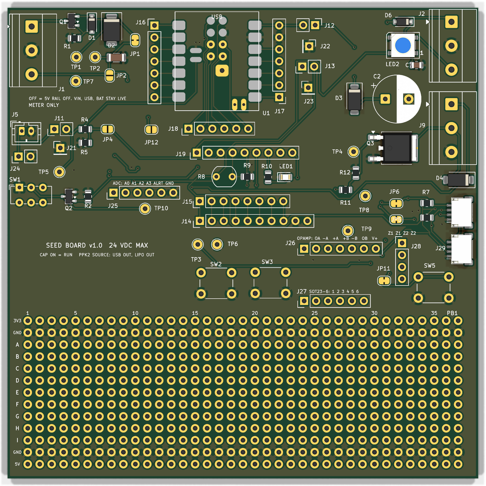
It's a small 10 cm by 10 cm board with a prototype area where you can put in any parts you're missing. The front side has the surface mount stuff that's, quote unquote, part of the board. All the through-hole stuff isn't soldered in at all, so you never have to solder it up if you don't want to or need to. I'll probably put in most of the headers. There are lots of them, so you can jumper things. All the pins on the chip are pulled out to a header that you jumper to a function on the board, like an LED or whatever. I think the only thing that's semi-hard-coded is the I2C.
You can power an LED strip, and there's a big enough cap there to keep your power supply stable while it's running whatever it runs. You can run servos and fans with PWM. The back is unpopulated but has footprints for some common chips, so if you want a dual op amp you can put one on, and it comes out on the headers. There's a battery section, a voltage-in section, and a spot for these little buck converters I get cheap. I've got a pile of them, so I may as well use them. So some of it's there because I have it, and some because I need it.
The big thing for me is power. I'll have a known working board (hopefully, I haven't tested it yet), and I can hang Nordic's PPK2 off it. I wish I'd had one of these about a million years ago. It's basically a multimeter for microamps, and that's absolutely required when I'm trying to put these suckers to sleep and run them on battery and solar.
If your board is plugged into a wall wart running ESPHome, I don't think this board's for you. It doesn't really matter if you're pulling a hundred milliamps or a full amp, you've got infinite power. But I'm exploring building these things with batteries, into toys that don't get plugged in very often, or LoRa nodes. I want to know how long the battery lasts with no solar, and what my solar budget needs to be so I never hit zero on a really long bad day in the middle of winter, wherever that winter might be. For a permanent install the panel and battery can be big, that's fine. When you're space-constrained, battery size and solar cell size make a difference. In a toy you probably won't have solar at all, so you just want to know how long this thing is going to be fun before you have to plug it in. Trial and error on something that lasts days is days of wasted time. Why not get it on the bench and let software figure it out for you?
The nice thing about the PPK2 is it also has logic inputs. Say you turn on an LED and that pin goes high. At the same moment you see how much current got used, because they're lined up together in the graph. Then you have a timer that says, one second after that, connect to a distant Wi-Fi, send a payload, and shut the Wi-Fi back down. The next thing in your graph after the LED is guaranteed to be your code, so now you know the Wi-Fi costs X. That's the kind of stuff I want to explore. I'm sure a million people have done this before, and I'm not pretending I'm not reinventing some wheel. But it's always fun to say I built that, I tested that, and here are my numbers.
More importantly, my AI learns what I learn. When I'm co-creating with AI and say we've got to make it do this and that, it'll know the budget, or at least be in the ballpark, and I think they're all going to be ballparks. The production rule is when in doubt, double it if you can afford it. Or if you want to run tight to the line, or you don't mind the battery dying, it dies at two in the morning and comes back to life with the sun. Every project has its own spec.
I didn't even look at the schematic this time, which is a huge leap of faith technically, but it mapped out nicely on the board. (Those are words to not live by.) It's off to JLCPCB now. If it works, you'll get another article. If it doesn't, you'll get an article about how badly it failed, because I've had a bunch of fails like this. I'm getting more confident in my hardware skills with this AI, though.
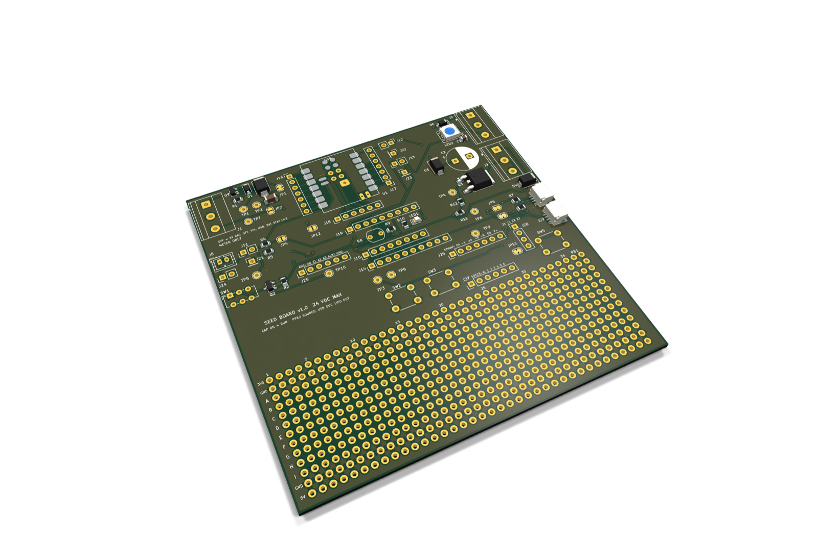
A different ESP32 could go on it just as easily if it has headers. Jumper ground and power to it, then jumper its pins to whatever pieces of the board you want to use. Through-hole chips you just want to play with go in the prototype area too, like a BCD to seven-segment decoder for an old-school display. You could even build an ATtiny programmer: solder on a little eight-pin harness, have the ESP32 program them, and do a whole bunch. And if I want to keep the battery section with its reverse polarity protection, I can pull it out into a small purpose-built board, so when I solder something together inside a little toy, it's already worked out.
The first job is power profiles of the chips, to see how close to zero I can get. I think one of the boards has an LED that always sucks power, that's my theory at the moment. So we'll poke at the chip until it's as quiet as it can be, then start removing parts until it's down to its spec'd sleep or deep sleep, whatever. And seeing how fast it wakes from an interrupt, that's cool, right?
Go make stuff.